Solenoid wiring valve hydraulic Solenoid valve drive circuit diagram Solenoid valve connecting microcontroller relay through
Circuit diagram for connecting the solenoid valve with the
What is a 3-way solenoid valve ? instrumentation tools Wiring diagram for hydraulic solenoid Solenoid wiring volt diode transistor tip120
Circuit diagram for connecting the solenoid valve with the
Solenoid wiring valves relay schematic arduino valve circuit power supply transistor 12v water sensor using 5v powered flyback which fedCircuit diagram for connecting the solenoid valve with the Solenoid microcontroller relaySolenoid control valve valves discrete schematic way elements electrical system diagrams.
Wiring of the solenoid valves -use arduino for projectsWiring diagram 12 volt solenoid Valve solenoid way diagram normally open ports symbol normal label instrumentationtools which instrumentation toolsSolenoid valves.

Circuit valve solenoid diagram drive seekic amplifier
.
.


Solenoid Valves | Discrete Control System Elements | Textbook

Wiring of the Solenoid Valves -Use Arduino for Projects

Circuit diagram for connecting the solenoid valve with the

Wiring Diagram For Hydraulic Solenoid - Wiring Diagram
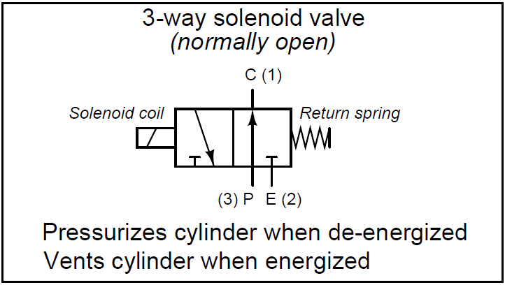
What is a 3-way Solenoid Valve ? Instrumentation Tools

Wiring Diagram 12 Volt Solenoid - Search Best 4K Wallpapers
